Case Studies
Etching Channels to Create an Air Bearing or a Hydrodynamic Seal
Popular categories
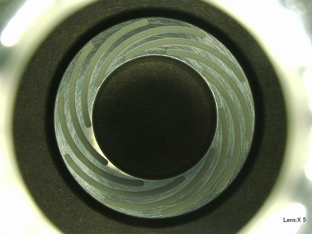
We’re not talking about the cute animals surfing the ocean waves, but are talking about bearing surfaces inside turbine engines. These bearings operate at high speeds in a harsh environment where traditional rolling contact or static bearings would not survive. To improve reliability and fuel efficiency specifically on jet engines, shallow channels are incorporated into the design in which air flows rather than traditional lubricants. The technical challenge is how to create these channels.
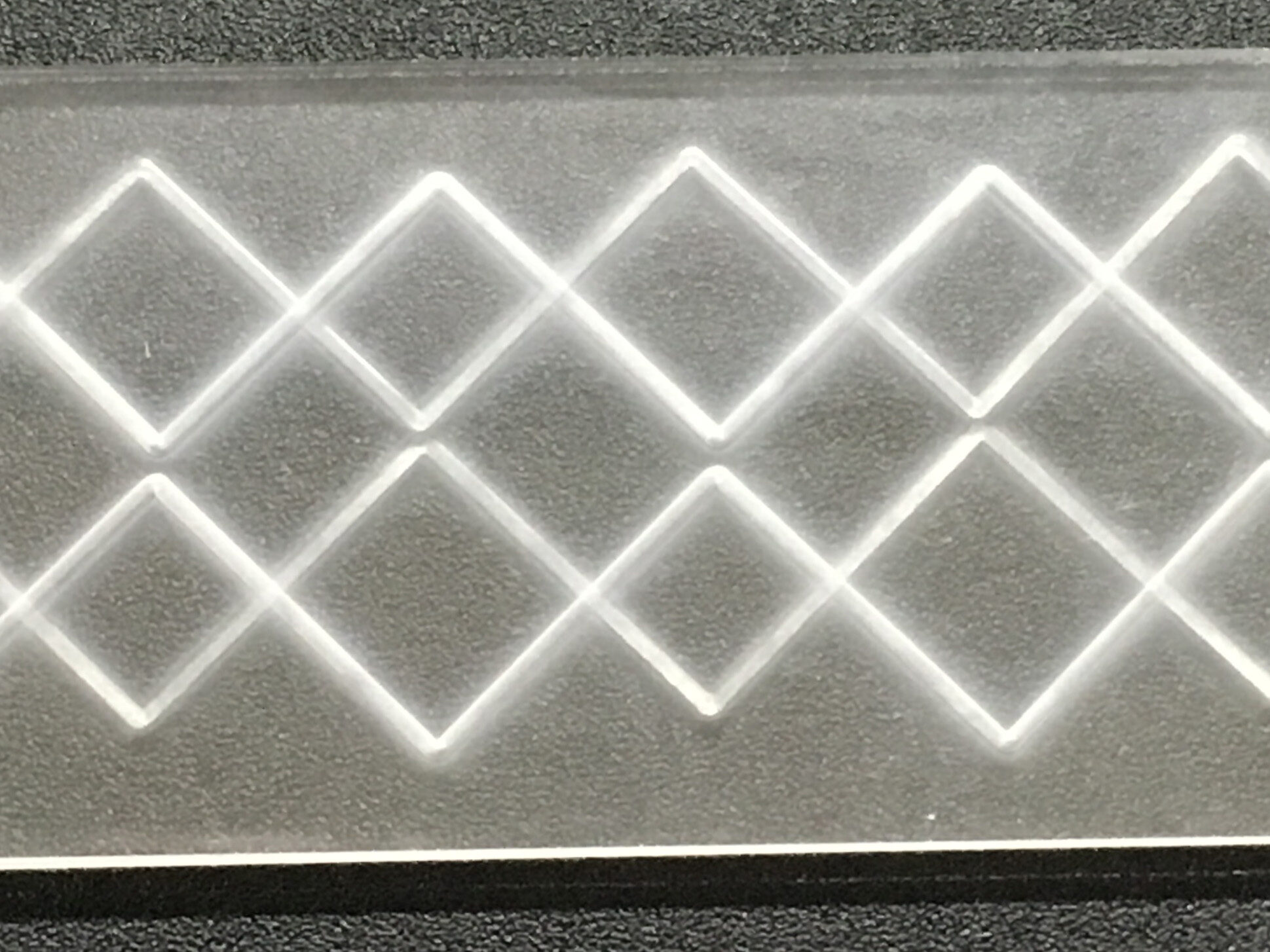
The consistency of channel depth and shape matters because any variation changes the lift-off height and causes vibration or wobble.
Why use air?
- Eliminates moving parts and bearing contact during operation = less wear or need for lubricants
- Improves stiffness and accuracy of motion = small bearing gap
- Reduces friction = no heat generation at high speeds
- Air = clean and contaminant free
The Challenges: Small Gap + Tight Tolerance
A liquid bearing can have a 100 µm bearing gap, but an air bearing can only have a 10 µm gap with a half of a micron tolerance. To top it off, most bearings are made of high-carbon steels or ceramics. Etching a flow path with a tight tolerance into these hard, brittle materials is not easy.
Possible Methods for Etching Channels
Several methods can be employed to etch these narrow channels including:
- Chemical etching
- Laser etching
- EDM direct machining
- Plasma etching
- MicroBlasting
Chemical etching is hard to control and erodes in all directions at an equal rate. Thus erosion will occur, not just creating a trench below the mask, but also under-cutting the mask itself. This method requires the use and disposal of non-environmentally friendly chemicals.
Laser etching and EDM direct machining are precise but expensive, and EDM can be slow to process.
Plasma etching is expensive, slow and requires an airtight, low-pressure chamber to contain the plasma.
The MicroBlasting Advantage
MicroBlasting is precision sandblasting on a micro-scale. It is designed to remove nanometers of surface material on small, intricate and delicate parts. It uses very fine abrasive media (17.5-25 µ for etching), focused nozzles (0.018″- 0.125″), and a consistent abrasive feed to remove microns of material with pinpoint precision, consistency, and control.
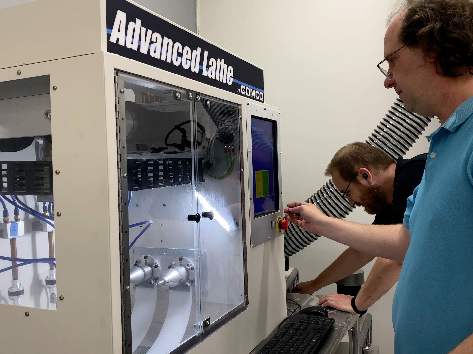
When paired with automation, MicroBlasting becomes a highly controllable process.
Removal rates can be set with tight tolerances (as low as half a micron) ensuring consistent results. Channel shape can be established with a stainless steel mask, allowing the blasting system to focus on maintaining a consistent depth.
Blast Parameters in this Case Study
Abrasive: 17.5 µ aluminum oxide
Blast Pressure: 70 psi
Nozzle distance to part: 1.0″
Nozzle size: 0.046″ Hi/Performance
Bypass tube: Medium (B)
Tank orifice: 0.030″
Nozzle speed: 0.5″/sec
Spindle speed: 450 rpm
Channel width: 1000 µm, dictated by mask
Results
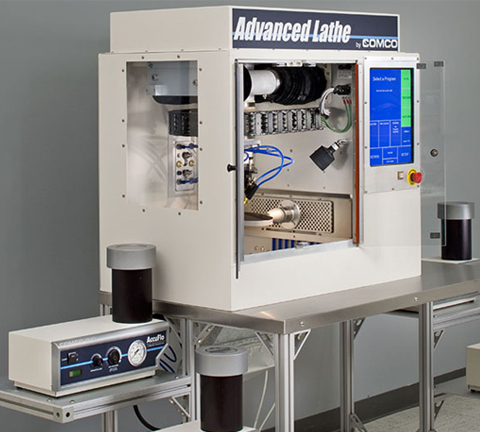
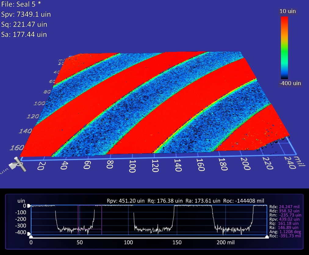
The Advance Lathe was set with the parameters listed above resulting in removal rate of 15 nanometers per pass of the nozzle. The sample was blasted until the channels reached a depth of 9 µm.
Because the part blasted in this case study was so small, we did not have to vary the nozzle speed as the nozzle passed over the part in order to create uniform channels.
Varying Channel Slope and Depth
Much like a child riding on the outer edge of a merry-go-round spins faster than a child sitting in the middle, as the seal spins on our lathe, the linear speed at the edge of the seal is greater than the inside. This means more abrasive per square inch hits the inside per second than the outside. Unlike the small sample presented above, larger bearing surfaces with greater differences in OD and ID may develop a change in slope due to this effect.
Automated systems can vary the speed of the nozzle as it moves over a part to create channels of uniform depth. This flexibility also allows the creation of sloped grooves.
For example, by increasing the nozzle speed as it moved from the inside to the outer edge of the bearing pictured at right, we created a channel depth that smoothly transitioned along the length of the groove from 17.5 µm at the ID to 2.5 µm at the OD.
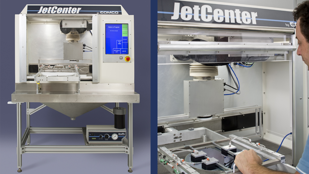
A Look at Automation
Sandblasting seems like a simple, uncontrollable process, but an automated MicroBlasting system provides laser-beam precision and process control needed to remove microns of surface material. Some benefits of Comco automated systems:
- built from a proven platform
- easily programmed and configured for specific applications
- offered as a turnkey solution, including tooling, blast head, and programming development
- multiple blaster options (though AccuFlo suits this application best)
- an easy-to-read touch screen display
- network compatible