Maintenance & Troubleshooting
FAQ AccuFlo
Popular categories
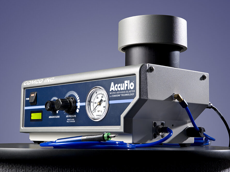

Our latest MicroBlaster, the AccuFlo®, is built to last, and we make sure that every blaster is ready-to-go after installation. However, each abrasive environment and application are unique. So, from time to time, an issue may arise.
A list of Frequently Asked Questions and potential solutions are loosely organized below. Click the question to see its answer in the drop-down box. Please use this as a starting point to perform simple maintenance on your own and better understand your Comco system.
If you need further assistance, please call 1-818-841-5500 or use the form below to contact our Technical Support Team.
General
How do I obtain a copy of the AccuFlo manual?
How do I set up my new AccuFlo?
- Read your equipment manual. (See previous question for links to manuals)
- Check out this post which walks through setting up a manual system (video included!)
- Before you begin blasting, read 5 Ways to Break Your Blaster for a quick guide on what not to do.
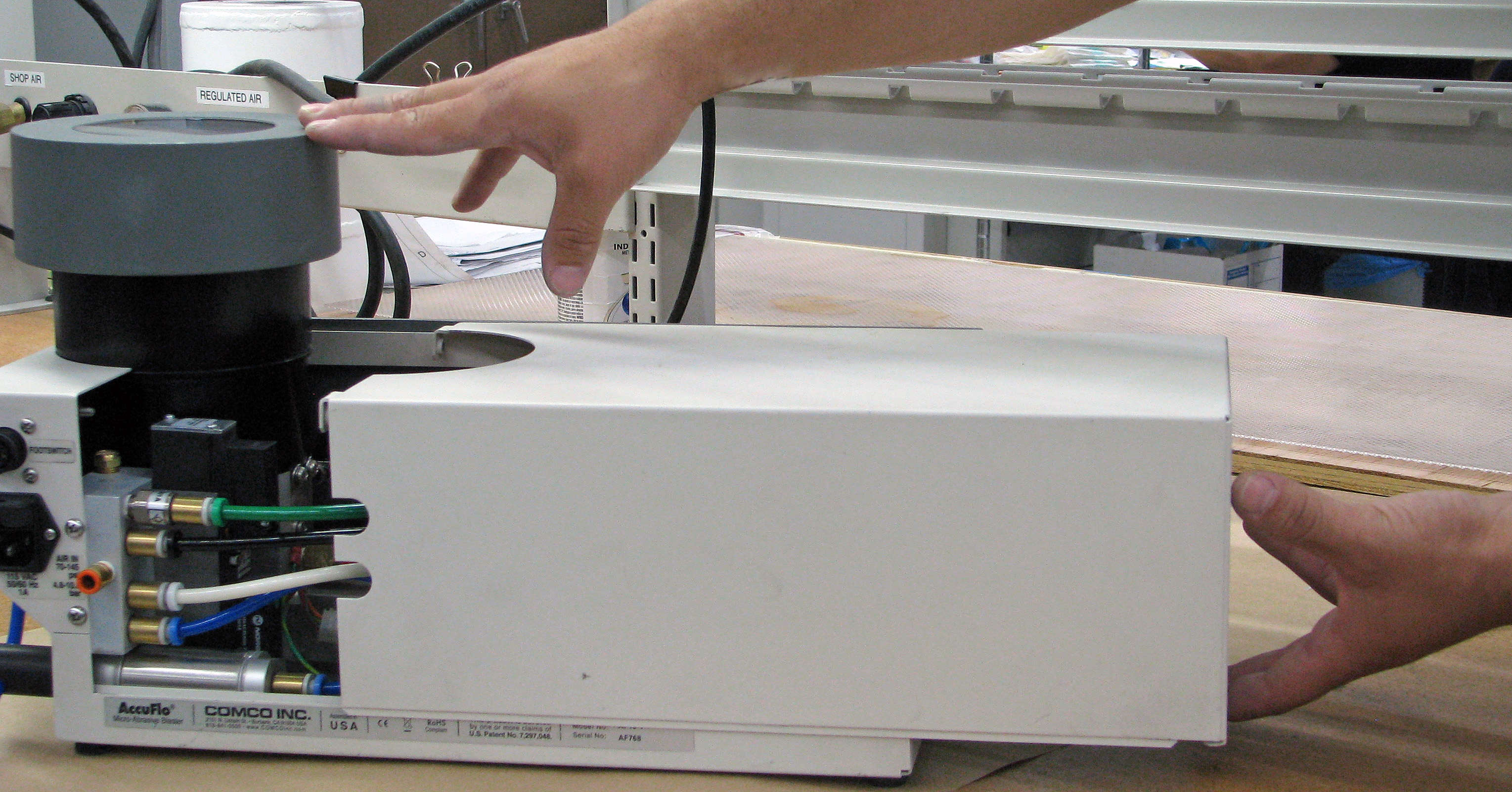
How do I remove my Machine Cover?
The AccuFlo cover slides off gently as one three-sided piece.
1. Loosen these two screws on the tank-side of the AccuFlo.
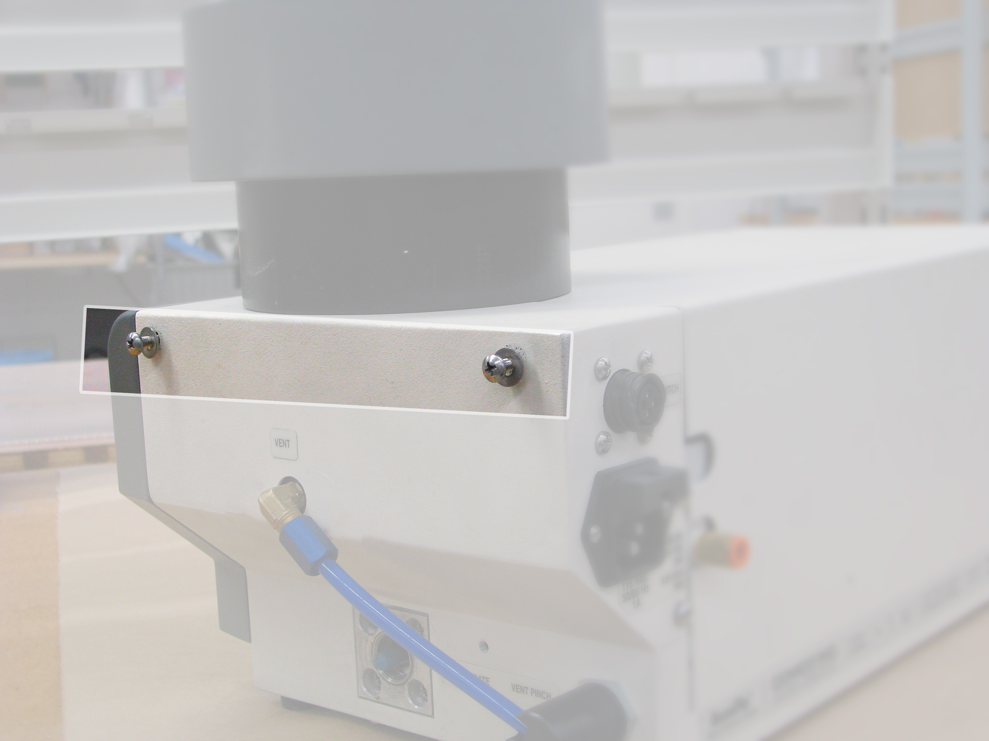
2. Brace the tank side of the unit with one hand and carefully slide the cover off with your other hand. Pull gently from the base.
Why do I need a Tune-up Kit?
The AccuFlo Tune-up Kit provides a backup of all wear items on the AccuFlo. A tune-up kit includes one of each of the following:
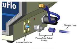
- PowderGate output fitting
- PowderGate nose piece
- Tank cover O-ring
Use this table to select the right kit for your AccuFlo model micro-abrasive blaster.
| Kit # MB2247 | Kit # MB2247-2 | Kit # MB2247-3 | |
|---|---|---|---|
| For 1/4″ output fitting (AF serial # up to 130) | For 1/4″ output fitting (AF serial # 131 and up) | For 3/8″ output fitting | |
| PowderGate Output Fitting | MB2560-2 | MB2560-3 | MB2560-4 |
| PowderGate Nose (Seal) | MB1653 | MB1653 | MB1653 |
| O-Ring | ST5650-242 | ST5650-242 | ST5650-242 |
To order a kit, contact Customer Service at 1-818-841-5500 or sales@comcoinc.com.
Where can I find a list of recommended Replacement Parts for the AccuFlo?
Click here to view a list of recommended replacement parts for the AccuFlo.
How do I change the abrasive?
Click here for our post on how to change abrasive. (Includes video demonstration.)
Abrasive and Air Stream Issues
How do I adjust the amount of abrasive in the air stream?
There are three points in the blaster where you can adjust the amount of abrasive in the air stream:
- Tank Orifice
- Bypass Tube
- Abrasive Blend Knob
All of the abrasive traveling from the mixing chamber and out to the nozzle must pass through the tank orifice; so this is the most important control point. The larger the orifice, the more abrasive in the air stream.
The bypass tube impacts the intensity that the modulator pulses have on the abrasive stream. It is easier for air to pass through the bypass tube to the top of the tank, where air dissipates. One of our large bypass tubes (size “C”) allows greater airflow, thereby reducing abrasive flow. Our small bypass tube (size “A”) creates a richer abrasive stream. Most applications need the midsize bypass tube, size “B”.
If you work with abrasives that clump often or do not flow easily; use a large tank orifice and a large bypass tube. The large tank orifice allows more abrasive into the mixing chamber, and the large bypass tube decreases the strength of the modulator pulse to keep the flow steady.
The next point of adjustment is the abrasive blend knob. See instructions in the next dropdown.
How far should I turn the Abrasive Blend Knob?
From 2024, all AccuFlo models ship with a calibration cap installed. There is no need to adjust it.
Learn more about the calibration cap.
If your blaster doesn’t have a calibration cap, we recommend turning the abrasive blend knob clockwise until it tightens. This is the maximum position.
Around 95% of our applications work best at the fully closed position which allows the most abrasive flow through the blaster.
To make adjustments to the abrasive in the air stream, change the tank orifice.
Learn more about tank orifice size and abrasive flow.
Why isn’t abrasive flowing out of the nozzle, but air is?
Is the powder tank empty?
Refill. (Easy fix- yay!)
Is the tank orifice plugged?
- Empty the powder, remove the orifice and inspect.
- The orifice should be at least 4x larger than the average particle size.
- Check out our Tank Orifice Selection Guide.
- Is moisture a problem? See block below.
Is the abrasive in the tank damp and sticking to the walls?
- Look through the clear tank cover. Are clumps in the abrasive visible?
- Replace with fresh powder.
- Check that the air dryer is working properly.
- See block below about moisture contamination.
Is moisture contaminating the powder?
- Determine the type of gas that is connected to the system (Compressed Air, Nitrogen or Carbon Dioxide). Compressed air can cause moisture in the line.
- GAS WARNING! Never connect to pure Oxygen. It will cause an explosion.
- The compressed air line is the most common source of moisture. Look through the clear tank cover for obvious signs of moisture like holes or cracks in the abrasive leading down to the orifice. If not obvious, carefully remove the tank cover without disturbing the abrasive in the tank.
- If there are obvious clumps, cracks or holes in the abrasive; moisture is more than likely in your air line.
- Read our page on moisture issues and compare the information with your air supply and powder storage conditions.
- STORAGE NOTE: Abrasive must be stored in a cool, dry environment. No bags or bottles should be left open. Abrasive should not be left in the tank over the weekend or during downtime.
- Is a desiccant or a membrane dryer installed on the line? If a desiccant dryer in use, the desiccant may need to be replaced.
- DRYER NOTE: Our process requires a dew point of -25°F, but refrigerant dryers provide a dewpoint of +35°F. A refrigerant dryer alone is not sufficient, and your system requires an accompanying desiccant or membrane dryer.
- If a desiccant or a membrane dryer are NOT installed, it is time to do so.
Is the modulator functioning
- NOTE ABOUT THE MODULATOR: The modulator creates pulses of air by alternating between an open and closed position that allows free flow of air to the mixing chamber and a close position that stops the flow of air to the tank. As the modulator wears, the core no longer sits tightly against the polymer seat. If the core cannot sit tightly, the modulator cannot generate proper air pulses. The operator may get an initial flow of abrasive from a pressure pulse generated when the pinch valve opens; but after that, abrasive may only pull into the system through gravity.
- Does the modulator audibly hum when the footswitch is actuated? If not, or if it rattles noisily, the modulator should be checked and probably replaced.
- Most modulators need to be replaced after 5,000 hours of operation.
Are you using abrasive from a manufacturer than Comco?
- Not all abrasive is designed for MicroBlasting. Industrial abrasives commonly have a greater percentage of fine and coarse particles, which impacts and interrupts a blaster’s performance.
- Consider switching to Comco abrasives. We use proprietary systems and tools to maintain the purity of all our abrasives, ensuring optimum performance.
- Learn more about the importance of quality abrasive.
Why are neither air nor abrasive exiting the nozzle?
Is the electrical power ON?
- Verify that the power switch is on. The power light should be illuminated. If it is not illuminated but the switch appears to be in the on position; then the power switch may be defective. Contact our Technical Support Team 1-818-841-5500 or techsupport@comcoinc.com if you suspect that is so.
- Examine the power cord. Is it connected? Is it damaged? If it is connected and does not appear damaged; then call our Technical Support team at the number above.
- Check the fuse.
- If the needle on the gauge is pointing to 0, turn the regulator knob clockwise until it registers pressure.
- Set the regulator to desired blast pressure.
Is the inlet valve working properly?
- Periodically desiccant may pass through the dryer and stick in the valve assembly. Remove the coil and body from the valve to check and clear trapped foreign particulate.
- If no foreign particulate appears to be trapped, check the valve to make sure the coil is not damaged. Replace if necessary.
- Remove the nozzle and look through it. You should see light shining through the hole on the tip. Keep in mind that you may see light through glass bead.
- If plugged, run a small wire through the nozzle hole to clear.
- Using Sodium Bicarbonate? Try soaking the nozzle in a mild acid, like vinegar, to clean. (Read our blog post on working with this abrasive.)
- If plugging continues despite changing out the nozzle; either the tank is releasing too much abrasive or the nozzle is too small to flow the type of abrasive you are using.
- Check out our Nozzle and Powder Brochure for a comprehensive list of sizes and options.
Is there a problem with the abrasive line?
- Disconnect the abrasive line and check the fitting to see if it is clogged or crimped. Remove the clog or straighten the crimp.
- CLEAN: Sodium bicarbonate plates at the output fitting over time. Remove and soak the fitting in a mild acid, like vinegar. Dry the fitting completely before reinstalling. (Failure to dry completely will cause it to plate out again quickly.)
- REPLACE: Cutting abrasive will gradually wear away at this fitting until its walls collapse and close the opening. If cleaning did not solve the issue and/or the fitting appears thin; replace the output fitting.
Is the tank pressurizing?
- When the machine is on, the tank should be pressurized.
- If the tank is pressurized, then the problem is between the tank and the nozzle. (Read and follow directions in boxes above.)
- If the tank is NOT pressurized, the problem is between the regulator and the tank. (Read and follow directions in boxes below.)
Is the modulator working properly?
- The modulator can become plugged with abrasive, prohibiting air from passing through.
- Remove the modulator and slide the core back and forth inside the body. If it does not slide easily, then the modulator is plugged and may require replacement.
- See the next FAQ and follow the instructions.
Call our Technical Support Team at 1-818-841-5500 or techsupport@comcoinc.com to inquire about next steps.
Why is the abrasive hose wearing out so quickly?
- Verify that the appropriate abrasive hose is in use. We only recommend using our brand of abrasive hose with Comco equipment. If unsure, call our Customer Service at 1-818-841-5500.
- Verify that the hose from the output fitting to the pinch valve is not pulled too tight or bent. A sharp bend creates a wear point.
- Inspect the output fitting for wear. If worn, it can crush the abrasive hose, creating excessive wear. Replace the fitting if necessary.
- WARNING: Do not cut off sections of the hose that appear worn and use the seemingly good hose.
- If wear and holes are visible in one section of the hose, then the entire hose is probably near eruption. Replace the entire hose or risk turning your blaster into a snow globe.
- If wear and holes are visible in one section of the hose, then the entire hose is probably near eruption. Replace the entire hose or risk turning your blaster into a snow globe.
- Inspect the pinch valve assembly. Any sharp edges on the plunger or pinch tube causes the hose to wear faster.
Why do I see premature wear on my output fitting?
Are you using 3/8″ abrasive hose?
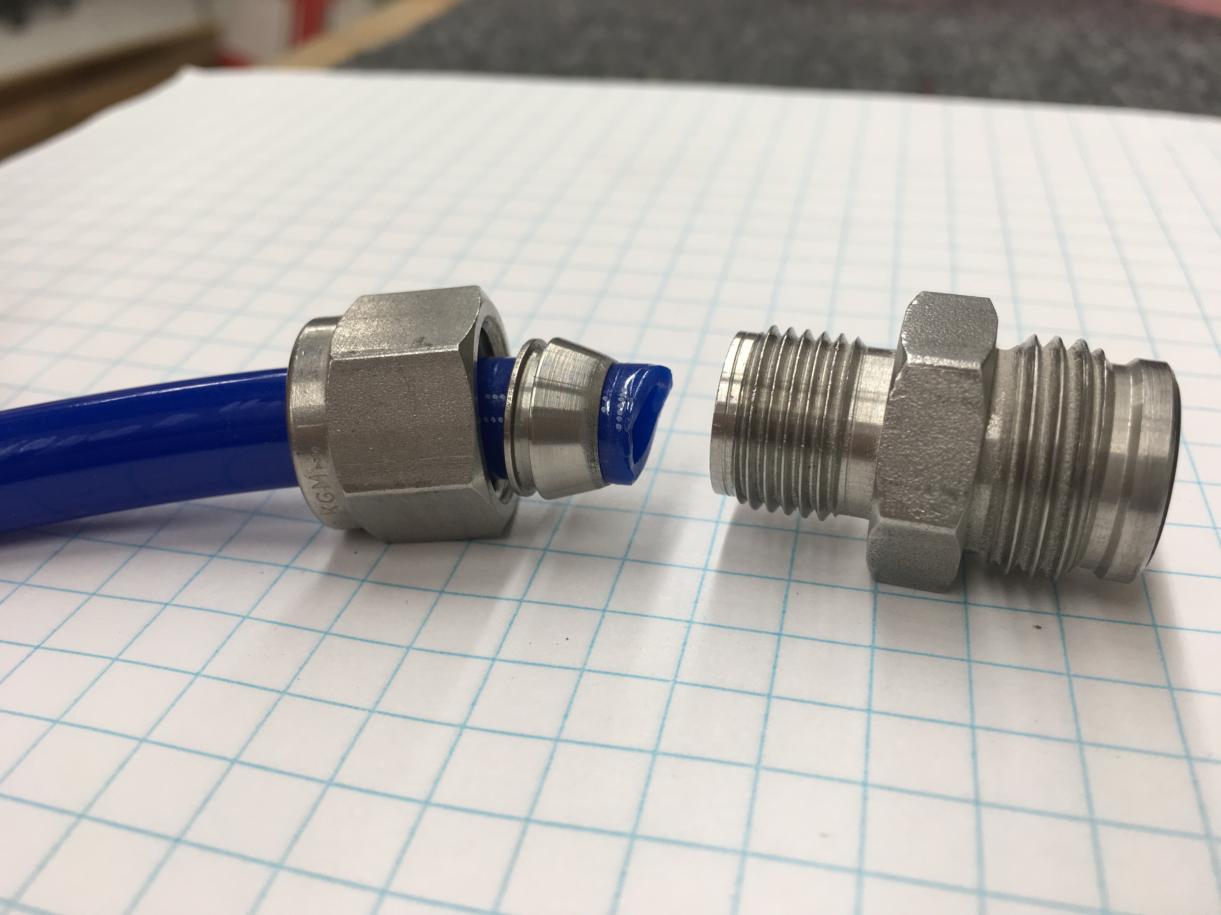
This larger abrasive hose requires a different type of connection than the QuickNut used on a standard 1/4″ hose. Proper installation for the larger hose fitting is critical. Installation requires 4 parts: the hose, the output fitting, a nut, and a 2-piece ferrule.
The 3/8″ abrasive hose must be pressed firmly into the output fitting prior to installation. Tighten the nut while holding the hose in place. The ferrule should crimp as the nut is tightened. Any gap between the hose and the output fitting creates turbulence in the abrasive stream and causes the fitting to fail along the side of the junction.
A poorly cut hose triggers quick wear. Check to see if the hose is cut raggedly or at an angle. The hose must have a straight, clean cut at its end.
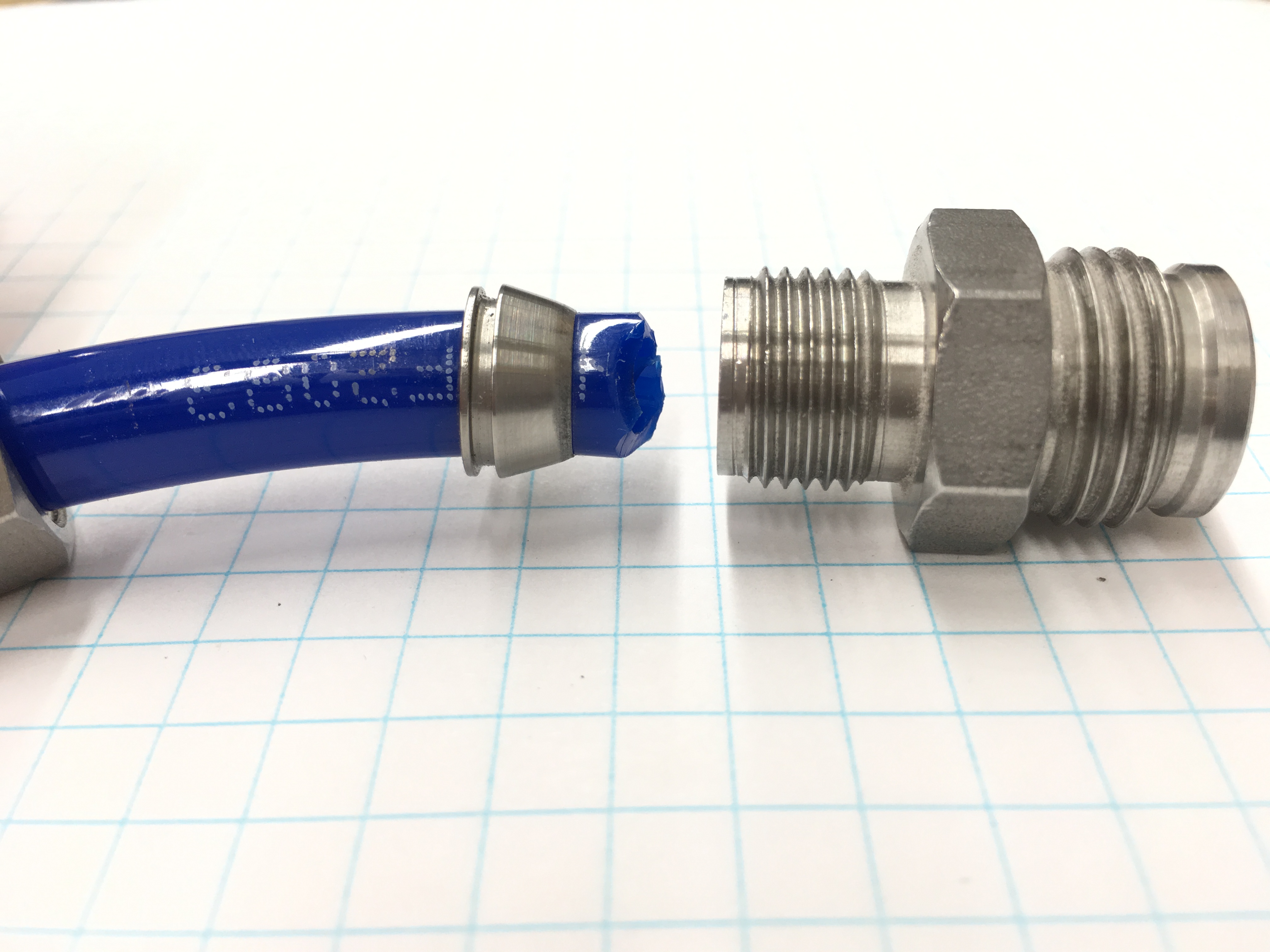 1. INCORRECT: A ragged cut will cause turbulence in the output fitting.
 2. INCORRECT: Cutting the abrasive hose at an angle will result in faster wear at the output fitting.
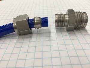 3. CORRECT: The hose end should be flat, straight and clean to fit securely in the fitting and reduce wear.
Don’t just cut the worn parts off!
If the hose is already damaged or visibly worn in one spot, even at its end, replace the entire hose. The first noticeable sign of wear is a good indicator that the entire abrasive hose is thinning all over, even if you cannot see these worn points. Don’t just cut off the visibly worn area and use the remainder of the hose. You risk turning your workstation and your shop into a sudden snowglobe.
If you are unable to resolve this or any issue, contact our Technical Support Team at 1-818-841-5500 or techsupport@comcoinc.com.
Why is too much abrasive in my air stream?
Make sure that orifice is screwed into place. If it is off-track, air and abrasive will travel around the threads. Inspect the orifice for wear. If worn, the opening will grow large. Replace the orifice if necessary.
What happens when my modulator wears out?
The modulator is a precision electro-magnetic valve that operates 50-60 times per second. This creates a pulsed air stream, fluidizing abrasive and drawing it from the tank to the mixing chamber.
- Diminished media flow after the first 5-10 seconds of blasting is a great indicator that the modulator is wearing out. A rattling sound is also a strong indicator.
- It should hum. If it rattles, replace it.
Learn more at Understanding Modulator Wear and Repair.
How does oil contamination affect my blaster, and how do I know if oil is contaminating my blaster?
Oil contamination causes clumps and clogs of abrasive at the orifice in the abrasive tank and in the nozzle. These clogs disrupt air flow and worse, may cause check-valve failure. Oil contamination prevents the check-valve from sealing properly, allowing abrasive to pass back through the system. The aggressive nature of abrasive quickly erodes the O-rings and seals on these components, resulting in costly repairs.To quickly spot oil contamination:
- Look at the air line. New air lines running clean air are milky-white in color. Exposure to oil turns these lines orange or yellow.
- Unscrew the black plastic bonnet inside the regulator to check for oil pools. Oil tends to pool in the regulator assembly of the AccuFlo.
- Open the assembly to expose the filter element. If large clumps of abrasive are stuck to the filter element, oil is present in your blasting system.
Learn more on Oil Contamination and the Importance of Clean, Dry Air.
Air Pressure
Why won’t my machine pressurize properly?
Is power getting to the unit? Does the light on the power switch illuminate?
- If not, check the power cord connections at the back of the unit and at the power source.
- Check the fuse and inlet air supply.
Do you hear air escaping from the unit when it is turned on?
- Check that the inlet air, vent hose and abrasive hose exiting the PowderGate valve are connected properly. (See pages 6-7 and of the manual that came with your machine for set-up.)
- Reminder: the hose from the Powdergate valve that runs directly to the nozzle should not route through the vent pinch. The vent hose should route through the vent pinch.
- Make sure the tank cover is securely fastened.
Why does my system have trouble maintaining consistent air pressure?
Why does my system have trouble maintaining consistent air pressure?
WARNING: The upper limit for air pressure is dictated by the house line pressure. There should be a 10 psi buffer between blast pressure and line pressure. Turning the regulator knob clockwise beyond the line pressure will not increase blast pressure and potentially damage the regulator diaphragm.
Does your regulator hold the proper pressure?
As the unit sits idle, does the pressure gradually creep up to line pressure, only to drop back down to the normal pressure once blasting begins?
- IF YES: there could be a problem with the diaphragm on the regulator. If the spring is not properly centered and air is leaking around it, pressure will increase to line pressure. Inspect the diaphragm and regulator assembly. Replace if necessary.
- IF NO: Contact our Technical Support Specialists at 1-818-841-5500 or techsupport@comcoinc.com.
Does the regulator stay at the desired blast pressure when idle, only to drop significantly once blasting starts?
- It is normal for the gauge to drop to 5-10 psi. For example, restriction in the line may cause a drop of 5-10 psi between idle and blasting states.
- If the drop is greater than 10 psi, then there may be insufficient air flow. Line pressure and volume may be too insufficient to support the current flow at the nozzle; and thus, pressure drops until it reaches equilibrium.
- Check the inlet air valve and regulator for a clog that could be restricting the air flow to the mixing chamber and nozzle.
- Check for leaks in the abrasive line going out of the nozzle.
- Check to make sure the nozzle has not been removed.
- If it has not been removed, check the nozzle size. The nozzle may be too large for the system.
- Check the inlet air supply to make sure it can deliver sufficient air volume. A 10 psi buffer should be maintained between blast pressure and supply pressure.
- Check the supply line from the compressor to the blaster. There could be a restriction, like a small diameter line, a partially open valve, etc.
Does the regulator drop less than 5 psi, but the air flow out of the nozzle is still weak?
- Inspect the check valve and filter assembly for a clog.
- Check for plating in the mixing chamber, the output fitting, hose and nozzle. Clean these areas, if needed, or replace those parts.
- Inspect the nozzle for clogs. Clean with a fine wire, if needed.
Nozzles
Why is a small amount of air leaking from the nozzle even though the blaster is not in use?
 This leak signifies a worn nosepiece or worn output fitting. Follow these steps to determine which part is worn.
- Unscrew the output fitting from the side of the machine.
- Using a pair of needle-nose pliers, pull off the blue nosepiece (which will have grooves).
- Replace the blue nosepiece.
- Inspect the carbide seat on the output fitting for grooves.
- If it has grooves, too, then replace the output fitting as well.
Contact our Customer Service Specialists at 1-818-841-5500 or sales@comcoinc.com to order replacement parts or a Tune-up Kit.
How do I change my nozzle?
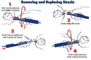
Instructions for replacing the AccuFlo nozzle on a ComfortGrip handpiece.
Can I use MicroBlaster nozzles on my AccuFlo?
Yes, but you need an adaptor. Contact our Customer Service Specialists at 1-818-841-5500 or sales@comcoinc.com to determine adaptations and order part #MB2331.
What size nozzles can I use with my AccuFlo?
- Standard AF nozzles range from .018-.060”.
- The AF is rated up to 7.5 SCFM.
- Remember, nozzle size + air pressure = air consumption. If using multiple nozzles, you may need to adjust your air pressure to keep it within the 7.5 SCFM range.
What range of nozzles are available?
Our nozzles come in an array of shapes and sizes for a wide range of applications. The straight, round style nozzle with openings ranging from 0.015″ to 0.125″ meets most application requirements. Rectangular nozzles are available for applications that require a wide sweep or fan of abrasive.
Comco offers long-lasting Hi/Performance nozzles in addition to standard nozzles. Hi/Performance nozzles deliver an accelerated abrasive flow with a tighter focus, resulting in less overspray. The lifespan of these nozzles is 3-5x longer than most standard nozzles.
Why is my nozzle wearing out so quickly?
Does the hose have a sharp bend?
A sharp bend in the hose just upstream from the handpiece will push all abrasive to the outside of the bend, wearing down the side that sees the most abrasive quickly.
Are you using rectangular nozzles?
- Due to their size, rectangular nozzles commonly wear faster than round nozzles. Once a wear characteristic starts to form in a nozzle, the characteristic will channel the abrasive through the location, accelerating the wear-rate.
- Two common wear patterns are the “football” and the “dogbone.”
- The football wear pattern occurs when the center of the rectangle wears faster than the edges. The center of the nozzle blows out quickly.
- The dogbone wear scenario occurs when the edges of the nozzle wear out faster than the center.
Power
Why is my machine not getting power?
Check your fuses located above the power receptacle on the back of the machine. It may be time to replace them. If the fuses appear to be blown, contact Customer Service at 1-818-841-5500 or sales@comcoinc.com to place an order. The part number for the fuse (220V, 5x20mm, 1A time delay) is ST2005-010.
If the fuses appear to be working and connected but the machine is not getting power, contact Technical Support at 1-818-841-5500 or techsupport@comcoinc.com.
Tank Cover
How do I mend a crack in my tank cover?
Do not attempt to patch or repair a cracked tank cover.
The window may require immediate replacement. Call our Customer Service Specialist at 1-818-841-5500 or sales@comcoinc.com to order a new tank cover window (part #MB2217).